


Call Center
02-518-0680
Call Center
02-518-0680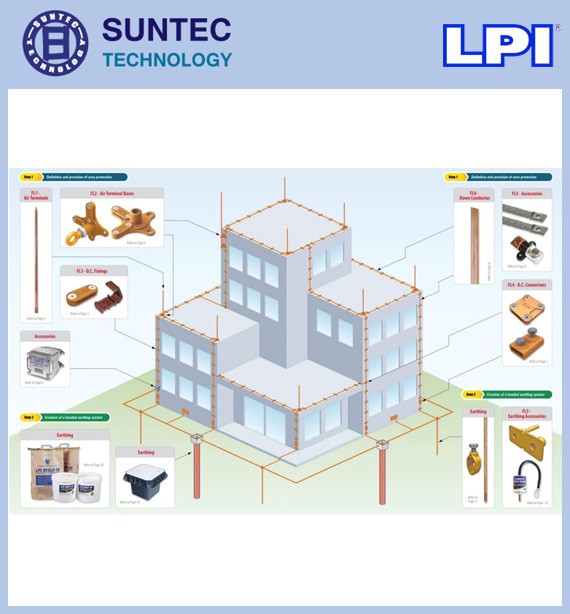
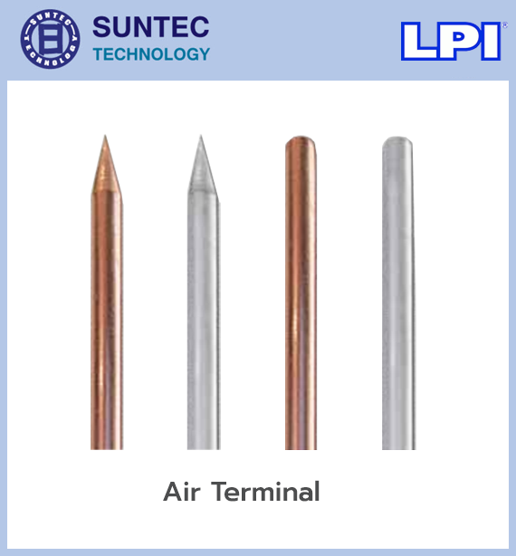
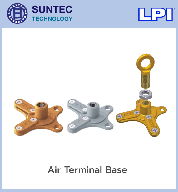
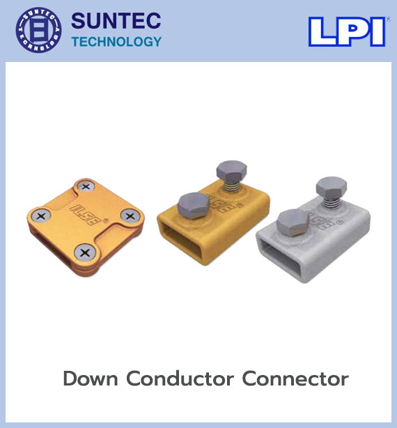
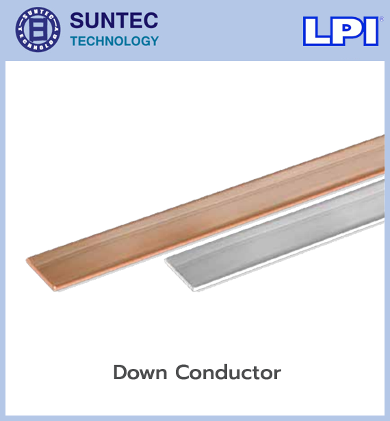
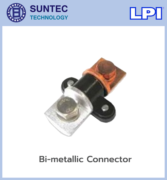
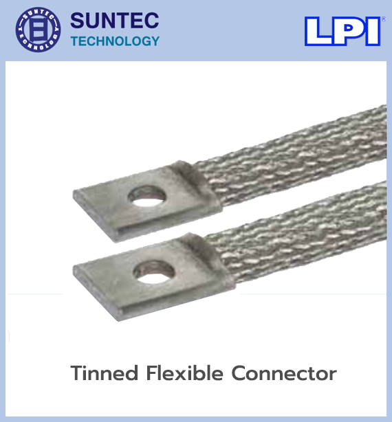
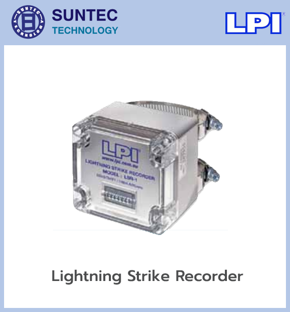


The Faraday Cage lightning protection system can be designed to EIT 2009-59, IEC 62305-3, NFPA 780 and ITU K.112. These standards offer several approaches to designing and installing a Faraday Cage system. Modern lightning protection equipment comes in many forms and materials. As well as choosing standard-compliant equipment, it has to suit the environment the system will be installed in. We provide a complete service: designing and installing Faraday Cage systems, maintaining them, and inspecting lightning protection systems with specialist tools certified to international standards.
A lightning protection system consists of:
1. Air termination system
Air terminal positions can be designed by the protective angle method, the rolling sphere method or the mesh method
2. Down conductor system
Down conductors should be evenly spaced, between 10 and 20 metres apart
Down conductor forms: solid round, solid tape and stranded
3. Earth termination system
Earth termination arrangements include radial and vertical electrodes, and ring or foundation earthing
LPI lightning protection equipment can be applied in designs following EIT 2009-59, IEC 62305-3, NFPA 780 and ITU K.112, with properties conforming to IEC 62561.
The Faraday Cage lightning protection system is the traditional, conventional approach. A metal conductor mesh is installed across the roof, connected to several down conductors and bonded into the main earthing system. When lightning strikes the building, the current is intercepted by the air terminal or the conductor mesh, then spread across several down paths before being discharged safely into the ground.
LPI (Lightning Protection International) groups this equipment under Conventional Systems, covering conductors, connectors, fixings, finial bases and lightning protection accessories.
The Faraday Cage system provides a continuous path for lightning current from the highest point of the building down to the earthing system, in this sequence:
The positions of air terminals and roof conductors can be worked out using the methods the standard sets out:
Conductors are installed as a mesh on the roof, creating a network that receives strikes across the building's area. It suits flat roofs and buildings with a large roof area. The mesh size must be set by the lightning protection level, not by the size of the building alone.
An imaginary sphere is rolled across the building's surfaces. Any point the sphere touches is treated as a possible strike point, so an air terminal or conductor has to be installed there. The radius of the sphere depends on the lightning protection level chosen.
The protected zone is defined by the angle beneath the air terminal. It suits structures or projections that are not complex in shape. The protective angle varies with the height of the terminal and the protection level.
A real design may combine more than one method, especially for buildings that are complex in shape or that carry a lot of equipment on the roof.
IEC 62305 divides lightning protection systems into four levels.
| Level | Protection level | Typical maximum mesh size | Rolling sphere radius |
|---|---|---|---|
| LPL I | Highest | 5 × 5 m | 20 m |
| LPL II | High | 10 × 10 m | 30 m |
| LPL III | Medium | 15 × 15 m | 45 m |
| LPL IV | General | 20 × 20 m | 60 m |
The appropriate level has to come from a risk assessment. It should not be chosen from the building type alone.
Installed at high points, corners, roof edges and anywhere likely to receive a strike, such as:
Air terminals must be installed with bases and fixings suited to the environment and the roof material.
The metal conductors run as a mesh across the roof, receiving the current and carrying it to the down conductors. Common materials are:
The choice of material has to take electrochemical corrosion into account, particularly where dissimilar metals meet.
The base that fixes the air terminal to the roof surface or structure. Several types are available to suit concrete roofs, metal sheet roofs, walls or specific structures.
Fixes the conductor to the roof and walls, keeping the spacing and the run stable. It should be designed to take mechanical load, thermal expansion and the outdoor environment. LPI supplies conventional system fixings both for structural fixing and for installation that reduces roof penetrations, depending on the product and the mounting surface.
Joins conductors in straight runs, at crossings, at branches and where they meet an air terminal or down conductor. Every joint must be mechanically strong and carry lightning current continuously.
Carries the current from the roof down to the earthing system. Several down conductors should be installed around the building so that the lightning current has parallel paths and spreads well. Key installation points are:
The number and spacing of down conductors must be set by the LPS level, the shape of the building and the standard in use.
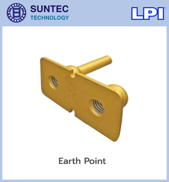
A test point between the down conductor and the earthing system, which can be separated to measure earth resistance and check conductor continuity. It should be installed where it can be reached for maintenance but is protected against impact, tampering and corrosion.
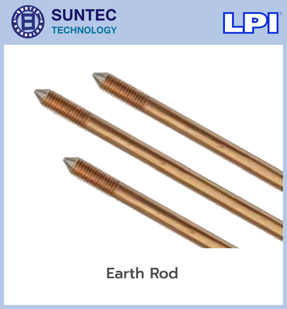
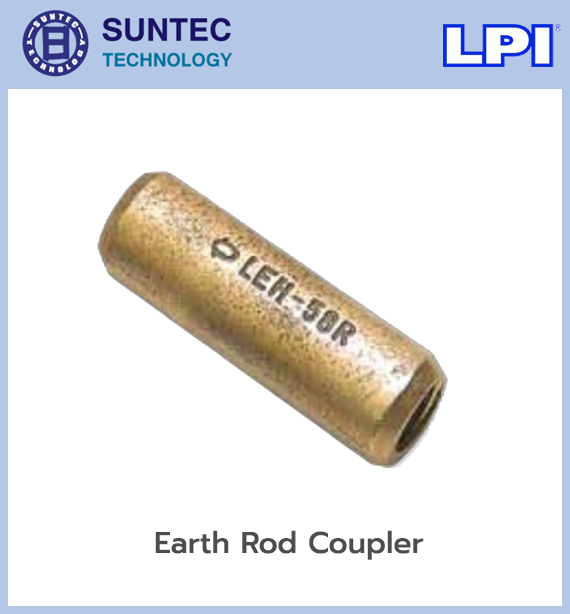
The earthing system discharges lightning current into the ground. It may consist of:
The design has to take soil resistivity, the installation area, corrosion and impulse current distribution into account. It should not be judged on a single earth resistance figure.
An inspection pit for checking and maintaining the earth connection. It protects the joint from damage and keeps the test point accessible.
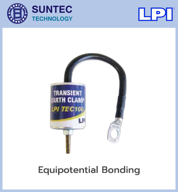
Bonds metal parts and the earthing system to a similar potential, reducing the risk of side flash. Items that may need bonding include:
The lightning protection earth and the electrical system earth should be bonded in line with the standard, to reduce dangerous potential differences. LPI states that earthing and bonding exist to create a low-impedance reference point and to reduce the potential difference between conductive parts.
The Faraday Cage handles a direct strike outside the building, but it cannot fully protect against surge voltage entering power, telephone or data lines. Surge protective devices should be installed as well, at points such as:
A UPS is not a direct substitute for an SPD, because an ordinary UPS may not handle the fast-fronted surge current of a lightning event.
LPI recommends that a complete lightning protection system cover four parts:
Installing air terminals on the roof without proper down conductors, earthing, bonding and SPDs therefore does not count as a complete protection system.
The system should be inspected on schedule and after significant events, such as a severe strike, building extension work or new rooftop equipment. Check:
The design should follow the standards required by the project specification or by law, such as:
LPI products reference several sets of standards, but the certification documents for each individual part number have to be checked. Do not assume every product carries the same certification.
In short, the LPI Faraday Cage system is a conductor-network lightning protection system covering the building. It receives the lightning current at designed points, spreads it across several down conductors and discharges it into the earthing system. Installed together with equipotential bonding and surge protection, it gives more complete protection for the building, the people in it and the electrical equipment inside.
We have long designed and installed nurse call systems, fire alarm systems
and lightning protection systems for both private companies and government agencies.
A metal conductor mesh is installed across the roof, connected to several down conductors and bonded into the main earthing system. When lightning strikes the building, the current is intercepted by the air terminal or the conductor mesh, then spread across several down paths before being discharged safely into the ground.
It can follow EIT 2009-59, IEC 62305-3, NFPA 780 and ITU K.112, which offer several design and installation approaches to choose from.
As well as choosing standard-compliant equipment, it has to suit the environment it will be installed in. We provide design and installation of Faraday Cage lightning conductor systems tailored to each site.
