


Call Center
02-518-0680
Call Center
02-518-0680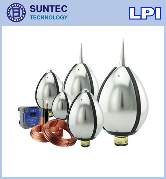
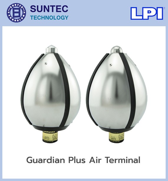
The Early Streamer Emission (ESE) lightning protection system uses air terminal technology that generates more streamer current than other types and works on a low impedance principle, giving a considerably wider protection radius. One air terminal mast therefore protects a wide radius, which also reduces the cost of the installation. To be effective, an ESE system must apply the protection measures of NF C 17-102 and use conductor materials meeting EN 50164-2 throughout.
LPI ESE lightning conductors protect effectively against lightning by covering four essentials:
1. Intercepting the lightning charge at the designed point
2. Carrying the lightning charge safely to earth
3. An earthing system that disperses the charge quickly
4. Preventing induced lightning current from harming people, objects or nearby electrical equipment
LPI Early Streamer Emission (ESE) air terminals are tested in a high voltage laboratory, with certificates and test reports to NF C 17-102, and properties conforming to IEC 62561-2. For our customers' peace of mind, we are glad to provide insurance cover of 10-50 million baht on every project where we install a lightning protection system.
The Early Streamer Emission (ESE) lightning protection system uses a high-performance air terminal installed above the highest point of the building. The terminal is designed to begin generating an upward streamer earlier than a reference air terminal under test conditions. It defines the designed strike point, then carries the current through down conductors into the earthing system.
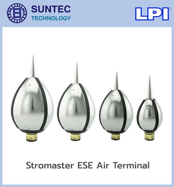
LPI's ESE products are branded Stormaster ESE, made from 316 stainless steel, with models graded by advance time: ESE-15, ESE-30, ESE-50 and ESE-60. LPI states that the products are tested to NF C 17-102:2011.
As the electric field between cloud and ground rises, a downward leader moves from the cloud towards the ground. At the same time, objects on the ground can produce an upward leader, or streamer. The ESE air terminal is designed to produce an upward streamer earlier than a reference terminal under defined conditions. The sequence is:
An ESE air terminal does not prevent lightning. It intercepts the strike within the designed area and provides a controlled path for discharging the current to earth.
The performance of an ESE terminal is expressed as ΔT, or advance time, in microseconds. It comes from comparing the time an ESE terminal takes to produce an upward leader against a reference air terminal, under the standard's test procedure. The main LPI Stormaster models are:
| Model | Stated advance time |
|---|---|
| Stormaster ESE-15 | 15 µs |
| Stormaster ESE-30 | 30 µs |
| Stormaster ESE-50 | 50 µs |
| Stormaster ESE-60 | 60 µs |
The figures 15, 30, 50 and 60 are ΔT values, not a protection radius in metres. The actual protection radius has to be calculated to the standard, taking into account:
So it is wrong to state that a given ESE model has a fixed protection radius on every project.
Design to NF C 17-102 divides protection into four levels.
| Level | Protection efficiency | Reference rolling sphere radius |
|---|---|---|
| LPL I | Highest | 20 m |
| LPL II | High | 30 m |
| LPL III | Medium | 45 m |
| LPL IV | General | 60 m |
LPL I gives a stricter protected area than LPL IV, so with the same ESE model at the same height, the radius calculated for LPL I is smaller than for LPL IV.
A high-performance air terminal installed on top of a mast, acting as the main strike point. LPI states the following properties:
Raises the ESE terminal above the highest point and any obstructions in the area to be protected. The height of the terminal above the surface affects the protection radius. The mast must be designed to take:
Raising the mast can increase the protected area, but not beyond the conditions of the calculation and the limits of the standard.
The base fixes the mast to the roof or structure. Taller masts may need guy wires or bracing for stability. Load-bearing capacity and waterproofing at the base must be checked with the structural engineer and the architectural team.
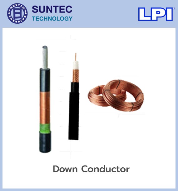
Carries the lightning current from the ESE terminal to the earthing system. It may use a bare conductor to the standard, or a specific conductor as the system design requires. Key points are:
NF C 17-102 generally requires at least two down conductor routes per ESE terminal where they can be installed, but the details must be confirmed against the building type, the project specification and the edition of the standard being referenced.
LPI offers HVSCPLUS, an insulated down conductor developed to carry lightning transient current. It is used where the separation distance has to be controlled, or where the risk of side flash near metal parts and internal systems has to be reduced. HVSCPLUS must be installed with the specified upper and lower termination kits, following the manufacturer's manual. It should not be jointed or modified like ordinary electrical cable.
Fixes the down conductor to a wall, mast or structure, controlling the run and preventing movement from wind and mechanical load.
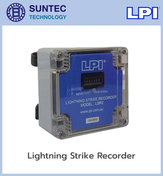
Counts the number of times lightning current has passed through the down conductor, as information for inspection and maintenance. Once the counter has increased, check:
A lightning counter does not protect against lightning and does not indicate the full severity of an event. It confirms that current passed through that path.
A joint that lets the down conductor be separated from the earthing system, so that continuity can be checked and the earthing system measured.
Receives current from the down conductor and disperses it into the mass of the ground. It may consist of:
The earthing system should be designed from measured soil resistivity, taking high-frequency current behaviour into account. It should not be judged on low-frequency earth resistance alone.
Bonds metal parts and the earthing system together to reduce potential differences, for example:
Bonding must follow the drawings and the calculations, to prevent side flash without creating an inappropriate current path.
The ESE terminal protects against the effects of a direct strike outside the building, but it cannot fully protect against surge voltage induced into, or entering through, the service lines. Surge protective devices must be installed as well, such as:
Selecting a surge protective device means coordinating the protection level, voltage rating, earthing system and the building's electrical system.
The ESE protection radius is not a fixed cylinder. It changes with the height being considered, so the protected area is a volume around the air terminal. The calculation to NF C 17-102 uses these key variables:
The radius has to be calculated separately at each level, such as the main roof, the plant room roof deck, the building edge and the ground. The radius at ground level should not be used to represent every level of the building.
LPI offers ESE design to NF C 17-102, with 3D drawings, a bill of materials and general specifications for each project.
Inspect on the schedule set by the standard and the maintenance plan, and also after a lightning strike or building refurbishment. The checklist includes:
LPI supplies an air terminal tester for checking supported models, following the manufacturer's procedure, but testing the terminal alone does not replace inspecting the whole system.
The main standard LPI cites for Stormaster ESE products is NF C 17-102:2011, and all four Stormaster models appear in the product category referencing it. What matters is that the various standards do not all recognise the ESE method in the same way.
Before choosing ESE, therefore, check whether the building owner, the consultant, the insurer, the local authority and the legal requirements accept NF C 17-102. A radius derived from NF C 17-102 must not be presented as a radius under IEC 62305 or any other standard.
In short, the LPI Stormaster ESE system intercepts lightning on the early streamer emission principle, designed to NF C 17-102:2011. It fixes the strike point and covers an area to the calculated radius. A complete system needs the ESE terminal, the mast, down conductors, an earthing system, equipotential bonding and surge protective devices, together with design, testing and maintenance to the standard the project accepts.
We have long designed and installed nurse call systems, fire alarm systems
and lightning protection systems for both private companies and government agencies.
It is an air terminal technology that generates more streamer current than other types and works on a low impedance principle, which gives it a considerably wider protection radius.
Because a single air terminal mast protects a wide radius, fewer installation points are needed, which reduces the cost of the lightning conductor installation.
Protection measures must follow NFC17-102, and the conductor materials used in each part of the system must meet the standards it specifies.
